Shaped Bandwidth Plots
In the following sub-sections results are displayed in the form of
UDT and multiple TCP bandwidth plots
as a function of the sum of the shaped TCP bandwidth taken over the
Iperf thread flows. The
bandwidth values are presented with average values that are calculated in the
areas with only UDT, only TCP, and
with combined UDT & TCP
traffic types. These flows are generated in the same way as described before in
the "Description" subsection. In
each plot the following plot traces are presented, entitled:
-
UDT (Only)
-
Contains the UDT bandwidth results
in the area with only this type of traffic.
-
UDT (& Iperf)
-
Contains the UDT bandwidth results
in the area where the
UDT & TCP traffic types
are combined.
-
Sum Iperf (Only)
-
Contains the sum over the TCP
Iperf flows in the area
with only this type of traffic.
-
Sum Iperf (& UDT)
-
Contains the sum over the TCP
Iperf flows in the area
with combined UDT &TCP
traffic types.
In the
plots of the average bandwidth values from the
UDT and / or TCP traffic types
listed above are presented as a function of
the shaped Iperf bandwidth
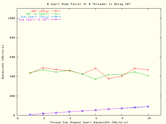
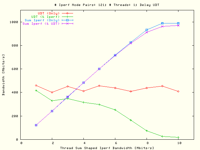
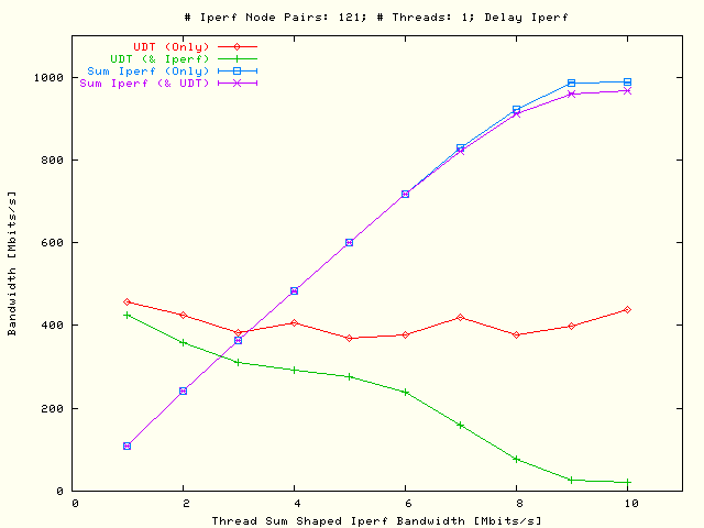
using one threaded parallel flow per node pair. The figures are displaying the
results of tests from 1 × 1 to 11 × 11 node
pairs as usual grouped into two VLAN's where each node is sending a TCP flow to
all other participating nodes in the opposite VLAN.
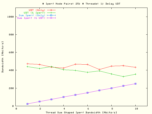
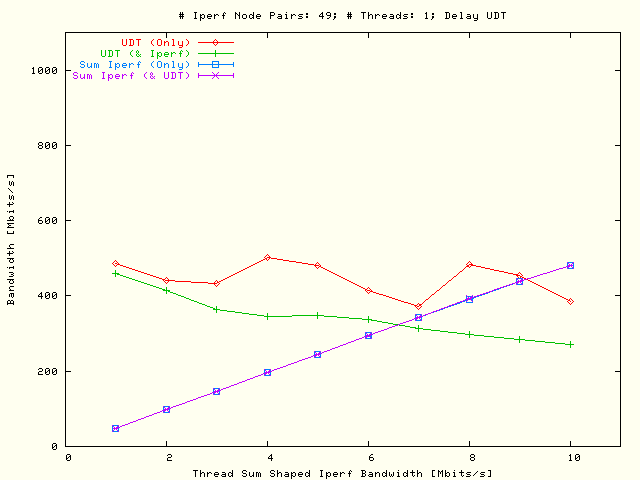
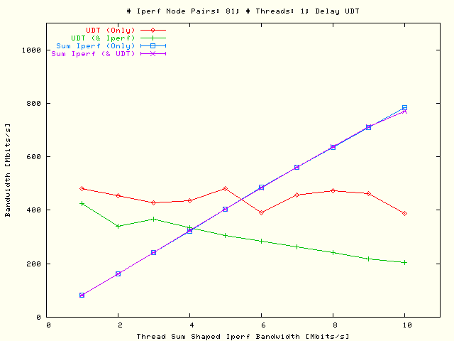
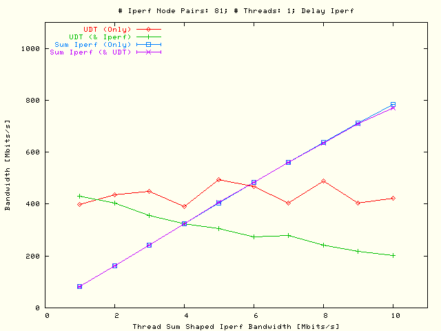
| . |
|
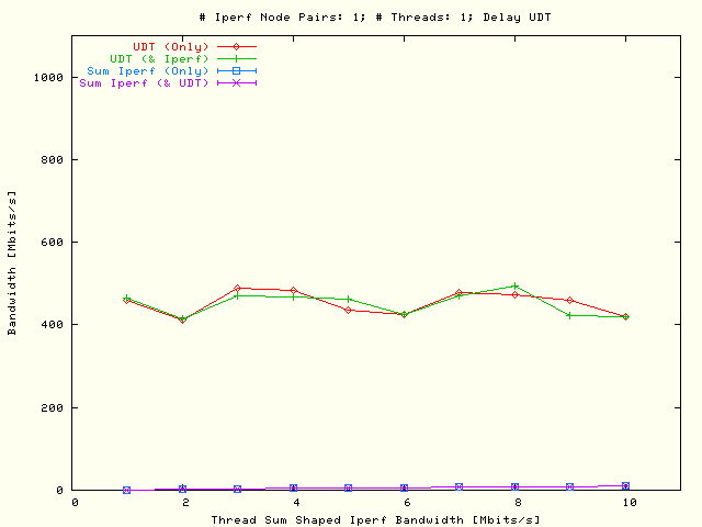
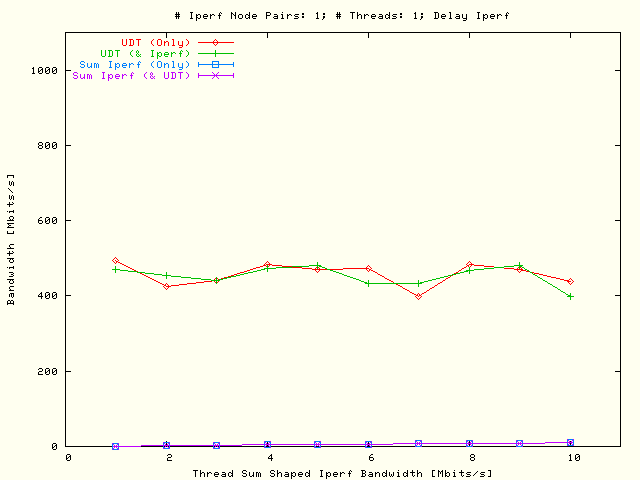
Single flow
UDT and multiple flows TCP
bandwidth as a function of the shaped
Iperf bandwidth sum
that is taken over the threaded parallel flows. In the left plot the
UDT flow has been delayed and
in the right plot the TCP flow which was defined by one parallel flow
per node pair. |
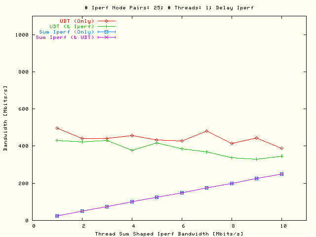
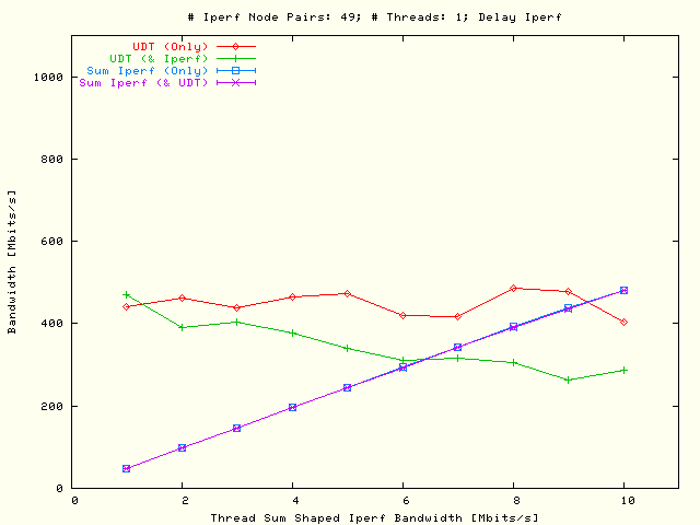
| . |
|
Single flow
UDT and multiple flows TCP
bandwidth as a function of the shaped
Iperf bandwidth sum
that is taken over the threaded parallel flows. In the left plot the
UDT flow has been delayed and
in the right plot the TCP flows which were defined by all possible
2 × 2 node pairs, using one parallel flow per node
pair. |
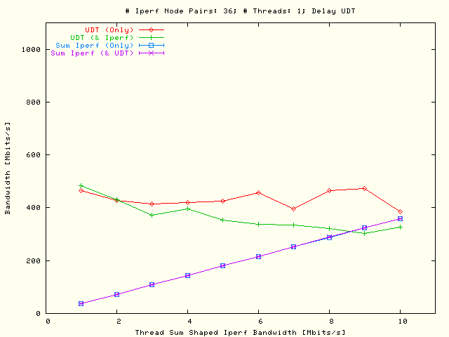
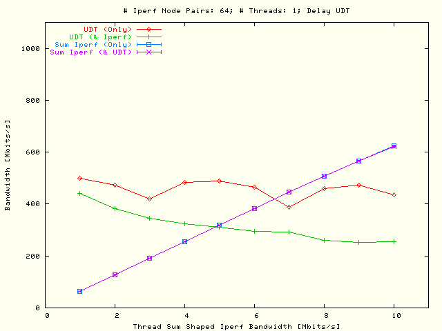
| . |
|
Single flow
UDT and multiple flows TCP
bandwidth as a function of the shaped
Iperf bandwidth sum
that is taken over the threaded parallel flows. In the left plot the
UDT flow has been delayed and
in the right plot the TCP flows which were defined by all possible
3 × 3 node pairs, using one parallel flow per node
pair. |
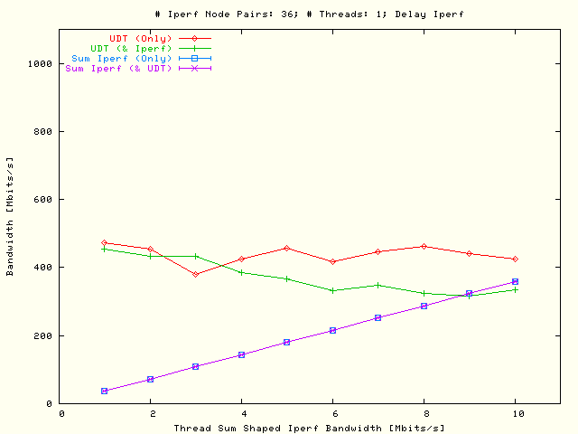
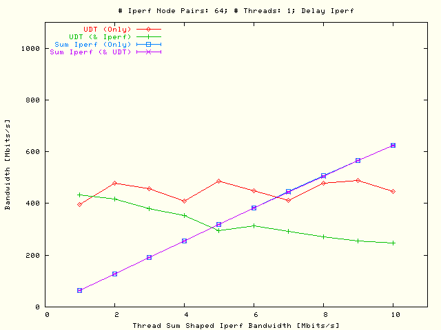
| . |
|
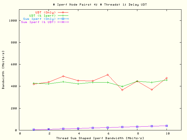
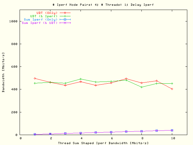
Single flow
UDT and multiple flows TCP
bandwidth as a function of the shaped
Iperf bandwidth sum
that is taken over the threaded parallel flows. In the left plot the
UDT flow has been delayed and
in the right plot the TCP flows which were defined by all possible
4 × 4 node pairs, using one parallel flow per node
pair. |
| . |
|
Single flow
UDT and multiple flows TCP
bandwidth as a function of the shaped
Iperf bandwidth sum
that is taken over the threaded parallel flows. In the left plot the
UDT flow has been delayed and
in the right plot the TCP flows which were defined by all possible
5 × 5 node pairs, using one parallel flow per node
pair. |
| . |
|
Single flow
UDT and multiple flows TCP
bandwidth as a function of the shaped
Iperf bandwidth sum
that is taken over the threaded parallel flows. In the left plot the
UDT flow has been delayed and
in the right plot the TCP flows which were defined by all possible
6 × 6 node pairs, using one parallel flow per node
pair. |
| . |
|
Single flow
UDT and multiple flows TCP
bandwidth as a function of the shaped
Iperf bandwidth sum
that is taken over the threaded parallel flows. In the left plot the
UDT flow has been delayed and
in the right plot the TCP flows which were defined by all possible
7 × 7 node pairs, using one parallel flow per node
pair. |
| . |
|
Single flow
UDT and multiple flows TCP
bandwidth as a function of the shaped
Iperf bandwidth sum
that is taken over the threaded parallel flows. In the left plot the
UDT flow has been delayed and
in the right plot the TCP flows which were defined by all possible
8 × 8 node pairs, using one parallel flow per node
pair. |
| . |
|
Single flow
UDT and multiple flows TCP
bandwidth as a function of the shaped
Iperf bandwidth sum
that is taken over the threaded parallel flows. In the left plot the
UDT flow has been delayed and
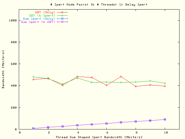
in the right plot the TCP flows which were defined by all possible
9 × 9 node pairs, using one parallel flow per node
pair. |
| . |
|
Single flow
UDT and multiple flows TCP
bandwidth as a function of the shaped
Iperf bandwidth sum
that is taken over the threaded parallel flows. In the left plot the
UDT flow has been delayed and
in the right plot the TCP flows which were defined by all possible
10 × 10 node pairs, using one parallel flow per node
pair. |
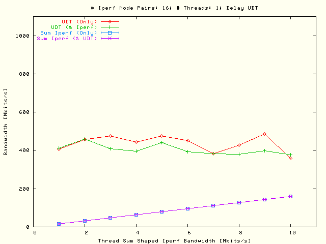
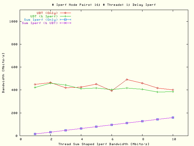
| . |
|
Single flow
UDT and multiple flows TCP
bandwidth as a function of the shaped
Iperf bandwidth sum
that is taken over the threaded parallel flows. In the left plot the
UDT flow has been delayed and
in the right plot the TCP flows which were defined by all possible
11 × 11 node pairs, using one parallel flow per node
pair. |
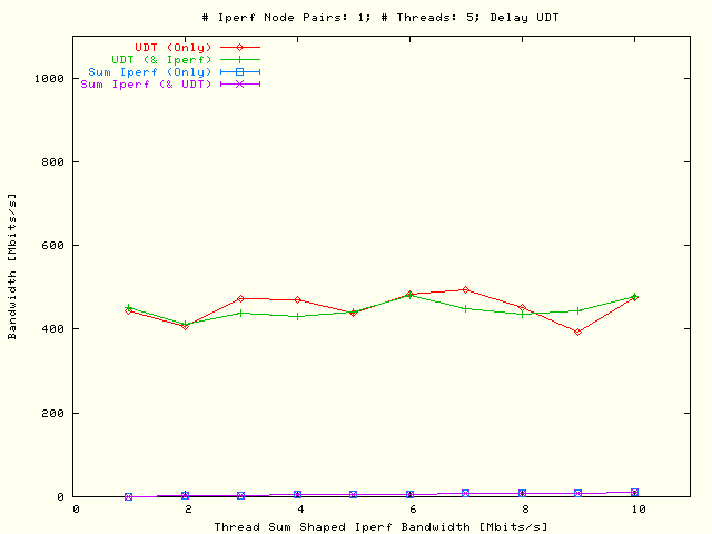
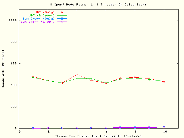
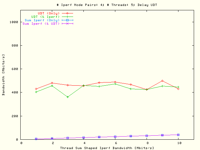
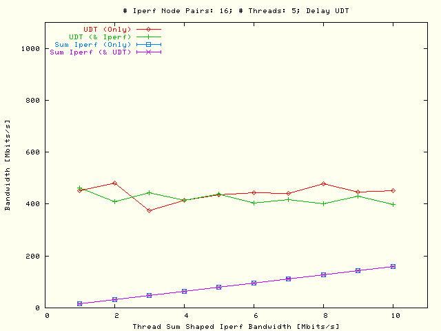
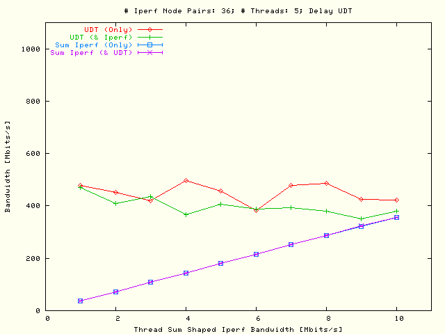
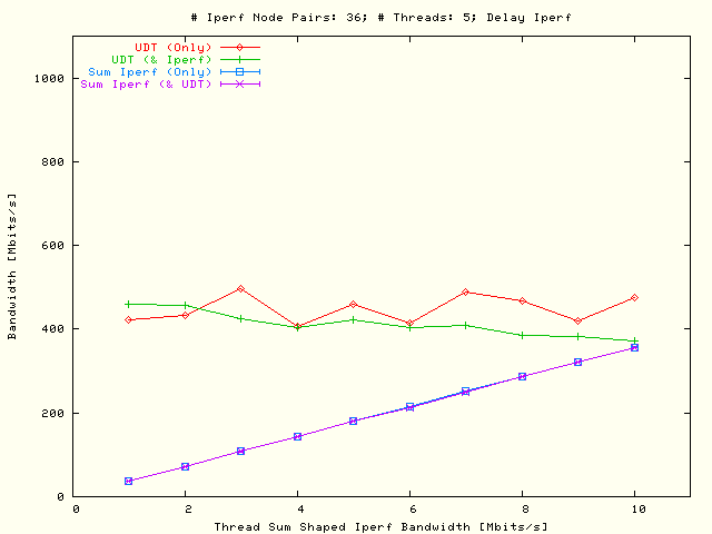
In the
equivalent results are displayed as in the
with the exception that there are now five threaded parallel TCP flows per node
pair used while in the previous situation only a single TCP flow per node pair
had been used with the constraint that the sum over all parallel flows per node
pair had been kept the same in both situations.
| . |
|
Single flow
UDT and multiple flows TCP
bandwidth as a function of the shaped
Iperf bandwidth sum
that is taken over the threaded parallel flows. In the left plot the
UDT flows has been delayed and
in the right plot the TCP flows which were defined by five threaded
parallel flows per node pair. |
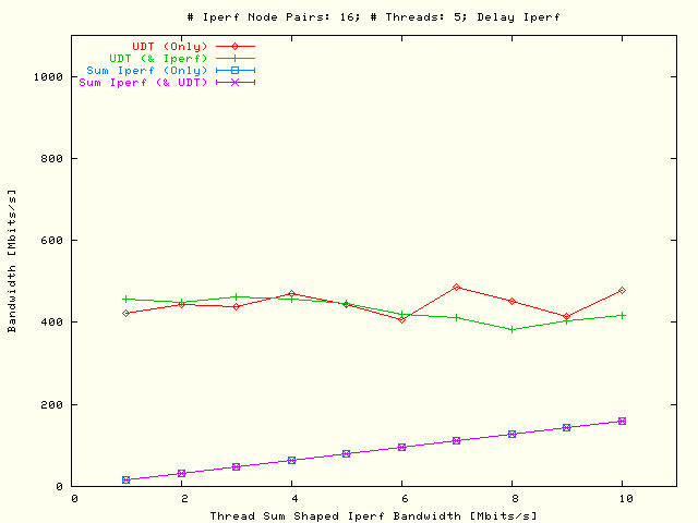
| . |
|
Single flow
UDT and multiple flows TCP
bandwidth as a function of the shaped
Iperf bandwidth sum
that is taken over the threaded parallel flows. In the left plot the
UDT flows has been delayed and
in the right plot the TCP flows which were defined by all possible
2 × 2 node pairs, using five threaded parallel flows per
node pair. |
| . |
|
Single flow
UDT and multiple flows TCP
bandwidth as a function of the shaped
Iperf bandwidth sum
that is taken over the threaded parallel flows. In the left plot the
UDT flows has been delayed and
in the right plot the TCP flows which were defined by all possible
3 × 3 node pairs, using five threaded parallel flows per
node pair. |
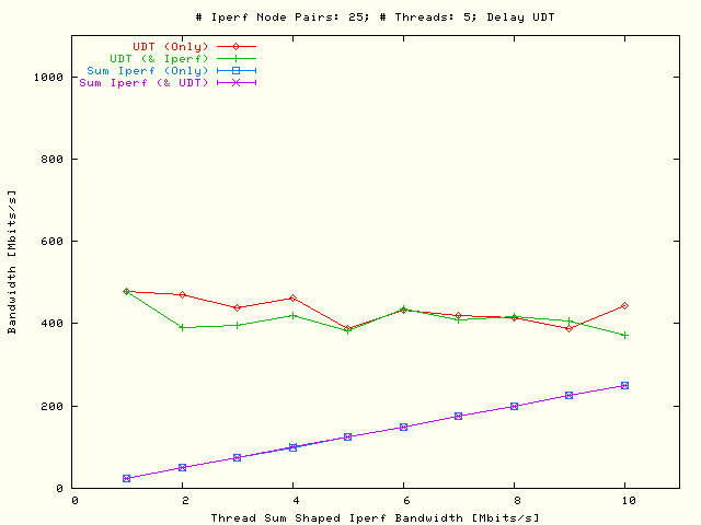
| . |
|
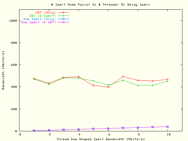
Single flow
UDT and multiple flows TCP
bandwidth as a function of the shaped
Iperf bandwidth sum
that is taken over the threaded parallel flows. In the left plot the
UDT flows has been delayed and
in the right plot the TCP flows which were defined by all possible
4 × 4 node pairs, using five threaded parallel flows per
node pair. |
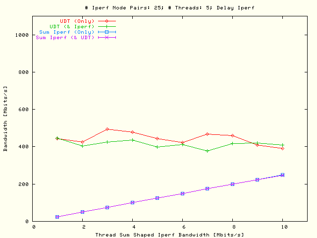
| . |
|
Single flow
UDT and multiple flows TCP
bandwidth as a function of the shaped
Iperf bandwidth sum
that is taken over the threaded parallel flows. In the left plot the
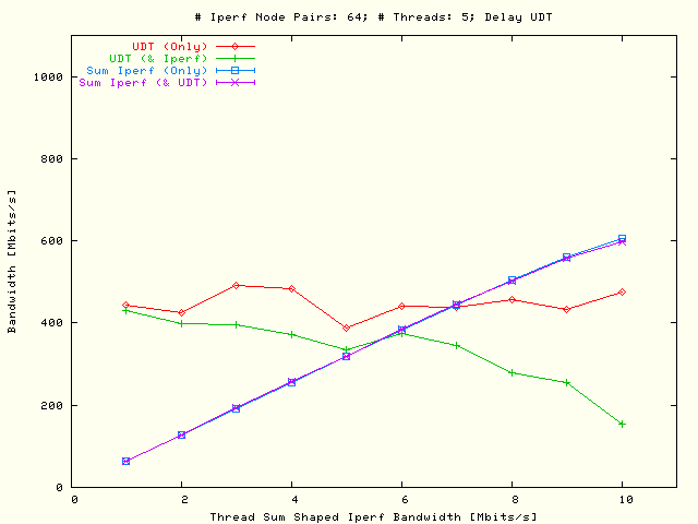
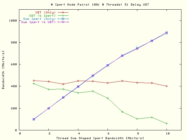
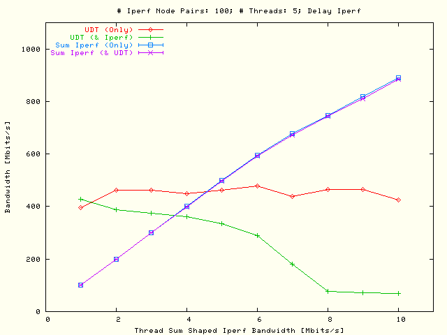
UDT flows has been delayed and
in the right plot the TCP flows which were defined by all possible
5 × 5 node pairs, using five threaded parallel flows per
node pair. |
| . |
|
Single flow
UDT and multiple flows TCP
bandwidth as a function of the shaped
Iperf bandwidth sum
that is taken over the threaded parallel flows. In the left plot the
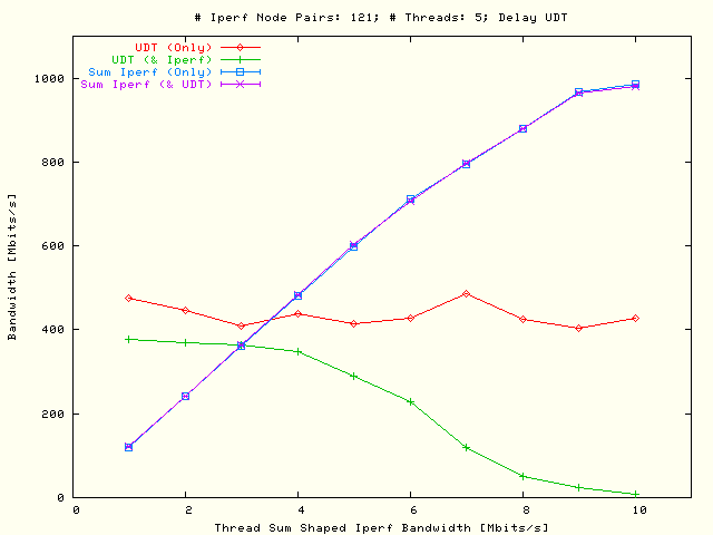
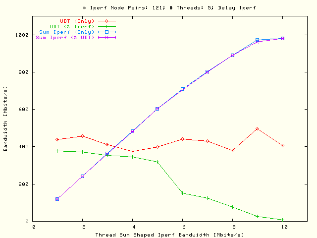
UDT flows has been delayed and
in the right plot the TCP flows which were defined by all possible
6 × 6 node pairs, using five threaded parallel flows per
node pair. |
| . |
|
Single flow
UDT and multiple flows TCP
bandwidth as a function of the shaped
Iperf bandwidth sum
that is taken over the threaded parallel flows. In the left plot the
UDT flows has been delayed and
in the right plot the TCP flows which were defined by all possible
7 × 7 node pairs, using five threaded parallel flows per
node pair. |
| . |
|
Single flow
UDT and multiple flows TCP
bandwidth as a function of the shaped
Iperf bandwidth sum
that is taken over the threaded parallel flows. In the left plot the
UDT flows has been delayed and
in the right plot the TCP flows which were defined by all possible
8 × 8 node pairs, using five threaded parallel flows per
node pair. |
| . |
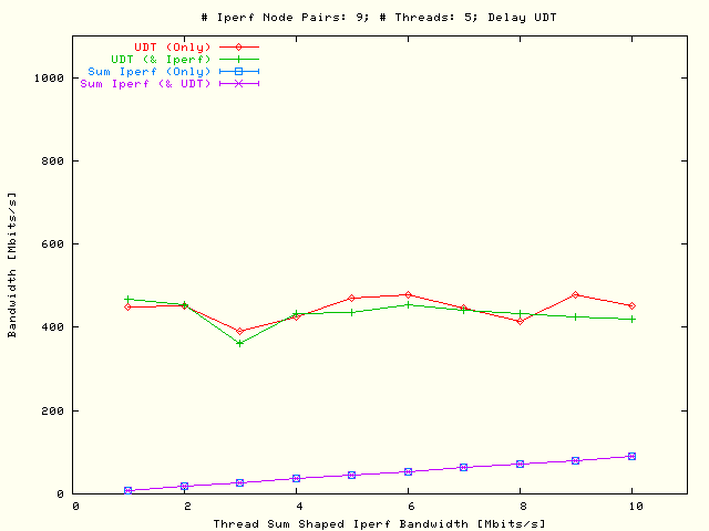
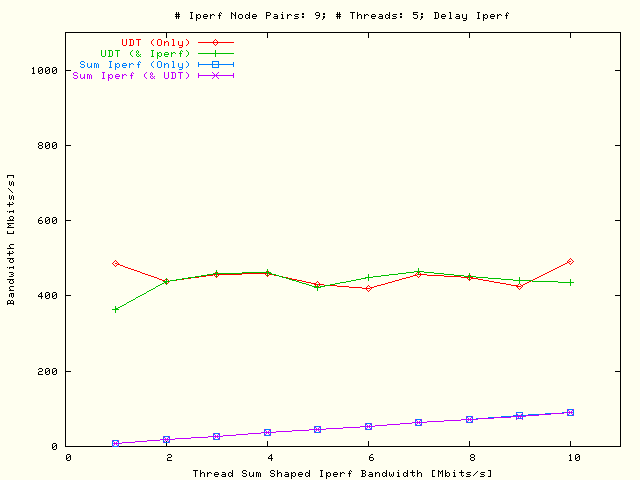
|
Single flow
UDT and multiple flows TCP
bandwidth as a function of the shaped
Iperf bandwidth sum
that is taken over the threaded parallel flows. In the left plot the
UDT flows has been delayed and
in the right plot the TCP flows which were defined by all possible
9 × 9 node pairs, using five threaded parallel flows per
node pair. |
| . |
|
Single flow
UDT and multiple flows TCP
bandwidth as a function of the shaped
Iperf bandwidth sum
that is taken over the threaded parallel flows. In the left plot the
UDT flows has been delayed and
in the right plot the TCP flows which were defined by all possible
10 × 10 node pairs, using five threaded parallel flows
per node pair. |
| . |
|
Single flow
UDT and multiple flows TCP
bandwidth as a function of the shaped
Iperf bandwidth sum
that is taken over the threaded parallel flows. In the left plot the
UDT flows has been delayed and
in the right plot the TCP flows which were defined by all possible
11 × 11 node pairs, using five threaded parallel flows
per node pair. |
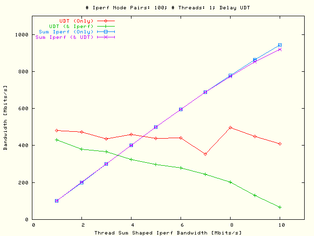
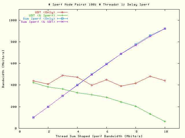
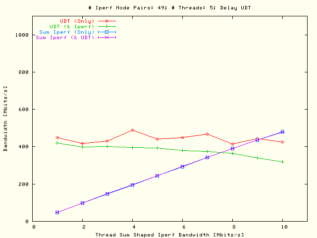
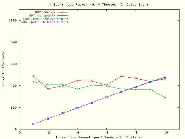
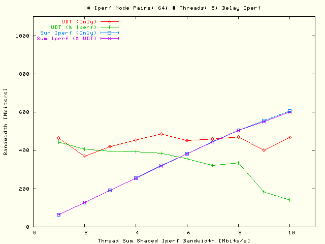
From the results in
the following conclusions can be drawn:
-
There is no significant difference in the results when the delay of the
UDT flows (left plots) are
compared with the delay of the TCP flows (right plots).
-
There is also not much difference in the
results for a single parallel flow
()
compared with the results for five threaded parallel flows
().
Only for a single parallel flow and with ≥ 10 × 10
node pairs, the sum of the TCP flows when combined with
UDT traffic is lower than the
corresponding sum without UDT
traffic, but this is only true for the larger shaped bandwidths.
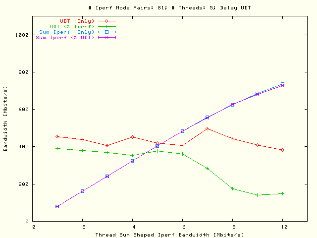
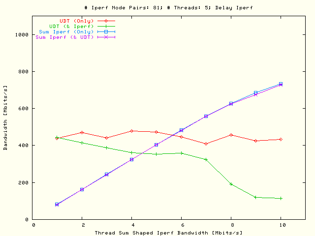
-
Besides the difference mentioned above,
there is no difference in the sum of the TCP bandwidth in the areas with or
without UDT traffic. Also the
UDT flow is completely pushed away
by the TCP flows.
-
Comparing the UDT bandwidth in the
areas with and without TCP traffic there follows for a single parallel flow
that there is a significant difference when ≥ 5 × 5
node pairs are used, and for five parallel flows when
≥ 6 × 6 node pairs are used. This is long before the
1 Gbits/s loop has been saturated.