5.3.1. Ideal Filters


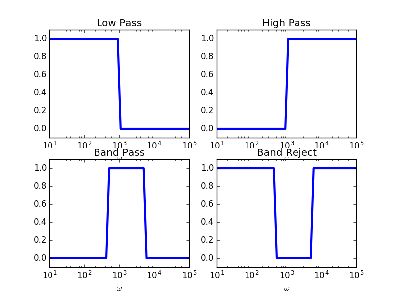
The basic ideal filters specified with their frequency responde are sketched in the figure below:
Ideal Low Pass Filter. All frequencies below \(w_c\) are left unchanged and all amplitudes of the frequencies larger then \(w_c\) are set to zero:
\[\begin{split}H(j\omega) = \begin{cases} 1 &: \omega\leq\omega_c\\ 0 &: \text{elsewhere} \end{cases}\end{split}\]Ideal High Pass Filter. A high pass filter is the opposite of the low pass filter:
\[\begin{split}H(j\omega) = \begin{cases} 1 &: \omega>\omega_c\\ 0 &: \text{elsewhere} \end{cases}\end{split}\]Ideal Band Pass Filter. The band pass filter passes the frequencies between \(\omega_L\) and \(\omega_H\) and suppresses all other frequencies:
\[\begin{split}H(j\omega) = \begin{cases} 1 &: \omega_L\leq\omega\leq\omega_H\\ 0 &: \text{elsewhere} \end{cases}\end{split}\]Ideal Band Reject Filter. The band reject filter is the opposite of the band pass filter:
\[\begin{split}H(j\omega) = \begin{cases} 0 &: \omega_L\leq\omega\leq\omega_H\\ 1 &: \text{elsewhere} \end{cases}\end{split}\]In practical applications often a band pass filter is designed to suppress one specific frequency. Such a very narrow band bass filter is often called a notch filter.