1.2. The Pinhole Camera Matrix
1.2.1. The Internal Camera Matrix
Consider the camera obscura again. In Figure Fig. 1.14 the plane with the small hole in it and the projection plane is shown (in this case the projection plane is on the left from the pinhole). The distance between the two planes is \(f\) (the focal distance).
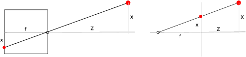
Fig. 1.22 On the left a physical model of the pinhole camera, on the right the virtual model where the projection plane is put in front of the ‘pinhole’.
The coordinate frame is chosen such that the origin \(O\) is precisely in the center of the hole. The \(Z\)-direction is along the axis perpendicular to the walls. The \(X\) and \(Y\) directions are in the plane of the wall. The projection wall is the plane \(Z=-f\).
If we know the real-world coordinates \(X\), \(Y\) and \(Z\) of point P, then it is possible to calculate the image coordinates \(x\) and \(y\) of the point \(P'\) projected onto the image plane \(I\):
The minus sign indicates that the projected image on the back of the pinhole camera (or camera obscura) is upside down. To get rid of this mirroring in our model (we are allowed to do that because we can mathematically correct for that anyway) we use a virtual pinhole camera in which the retinal plane is put at \(Z=f\), i.e. in front of the pinhole. In this model we have:
From a geometrical point of view a pinhole camera is thus characterized with a point (the origin or pinhole) and the projection plane. The distance between the point and the plane is the focal distance.
Using homogeneous coordinates we may model the ideal pinhole camera with:
The above pinhole camera model is a geometrical model: the coordinates (\(X,Y,Z\) and \(x,y\)) and the focal length are measured in meters (or millimeters or..). In practice the camera coordinates \((x,y)\) are measured in pixel distances (the sampling distances \(\Delta x\) and \(\Delta y\)).
To convert to pixel distances the scale factor \(s_x\) and \(s_y\) are introduced:
Note that now \((x,y)\) are measured in pixel coordinates. Often we write \(f_x=s_x f\) and \(f_y = s_y f\) leading to:
Pixel coordinates are not given with respect to a frame that is centered at the optical axis, instead the coordinates are in the positive quadrant. This implies a translation of the coordinate frame:
Finally we need to introduce a skew factor \(\alpha\) that accounts for a shear of the coordinate system (that might occur in case the optical axis is not precisely perpendicular to the retina). Thus we arrive at the following internal camera model:
where \(K\) is the internal camera matrix:
Exercises
Consider the internal camera matrix:
\[\begin{split}\matvec{cccc}{ 5 & 0 & 0 & 0\\ 0 & 5 & 0 & 0\\ 0 & 0 & 1 & 0 }\end{split}\]and consider 25 points in 3D space arranged on a regular grid in a plane. This plane passes through the point \((0,0,50)\) and is spanned by the two vectors \((1,0,0)\) and \((0,\cos(\theta),\sin(\theta))\). The points are:
\[\{(X,Y,Z)\} = \{ (5i, 5j\cos(\theta), 50+5j\sin(\theta)) \bigm| i,j=-2,-1,0,1,2\}\]- Fill in: for \(\theta = \ldots\) the 25 points are in a plane parallel to the retina. Let this value be \(\theta_0\).
- Calculate the projections for these 25 points for \(\theta=\theta_0\) and plot these points.
- Now consider \(\theta=\theta_0+ k \frac{\pi}{16}\) and calculate and plot the projected points for \(k=0,1,2,3,4,5,6,7,8\).
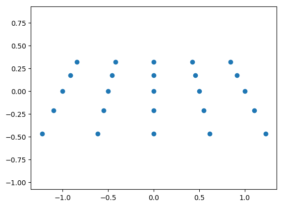
The answers can be deduced from the source code that produces the plot below for \(k=6\) in the last question. Please try to figure out for yourself why the points on the top row are more closely spaced together then the points on the bottom row.
In [1]: from pylab import *

In [2]: K = array([[5,0,0],[0,5,0],[0,0,1]])
In [3]: def plotpoints(k):
   ...:     th = k*pi/16
   ...:     XYZ=array([(5*i,5*j*cos(th),50+5*j*sin(th)) \
   ...:           for i in range(-2,3) for j in range(-2,3)]).T
   ...:     xys = dot(K,XYZ)
   ...:     xy = 1.0*xys[:2,:]/xys[-1,:]
   ...:     plot(xy[0], xy[1], 'o')
   ...:     axis('equal')
   ...:
In [4]: plotpoints(6)

In [5]: show()
Consider the internal camera matrix:
\[\begin{split}\matvec{cccc}{ 5 & \alpha & 0 & 0\\ 0 & 5 & 0 & 0\\ 0 & 0 & 1 & 0 }\end{split}\]and consider the points \(\{(X,Y,Z)\} = \{(5i,5j,1000) \bigm| i,j=-2,-1,0,1,2\}\).
- Plot the projected points \((x,y)\) for \(\alpha=0\) and \(\alpha=1\).
- Explain why the shear introduced by a non zero \(\alpha\) can only approximate the deformation caused by an optical axis that is not precisely perpendicular to the retina (projection plane).
1.2.2. The External Camera Matrix
Our pinhole camera model thusfar is represented with the projection:
where \(K\) is the internal camera matrix:
The problem with this matrix is that it assumes we can represent points in 3D space in coordinates with respect to the camera frame where the \(Z\)-axis is the optical axis (that is why we have used \((X_c,Y_c,Z_c)\)). Unfortunately in practice it is hard if not impossible to determine the geometry of the camera. I.e. we cannot measure what coordinate axes are (you have to open up a camera to start with).
Assume we know the 3D coordinates of points with respect to an arbitrary frame (often called the world frame). The camera frame is a rotated and translated version of this world frame. Let
be the frame transform that transforms the world frame into the camera frame. Then the coordinate transformation is the inverse of this transform. So a point \((X, Y, Z)\) in world coordinates has coordinates:
and thus the projection of \(\hv X\) on the retina is:
This can be simplified to:
where we have redefined the internal matrix \(K\). The matrix \((R\T\;-R\T t)\) is called the external matrix and the matrix \(P = K\,(R\T\;-R\T t)\) is called the camera matrix.
Exercises
Consider the situation that we have a camera that is moving around in a scene taking pictures of the same object in the scene (think of yourself taking pictures with your mobile phone while moving around). The world frame is fixed with respect to the scene.
- What part(s) of the camera matrix is (are) changing while you move around.
- When you keep your camera in the same position and orientation but you zoom in what is changing then?
Consider a cube with vertex points \((i,j,k)\) where \(i,j,k=0,5\) given in world coordinates. The world frame has \(Z\)-axis pointing upwards.
Consider a camera with internal matrix:
\[\begin{split}K = \matvec{ccc}{ 5 & 0 & 0 \\ 0 & 5 & 0 \\ 0 & 0 & 1 }\end{split}\]and position it point \((50,0,0)\) in the world frame and aim it to the origin (i.e. the camera \(Z\)-axis should be pointing to the origin of the world frame.
- Determine the external matrix numerically.
- Make a 2D plot of the projections of the 8 vertices of the cube.
- It is going to look a lot better in case you make a wire frame plot of the cube, i.e. connect the vertices with a line (except for all diagonals).
- What happens when you move the camera towards the cube? And what when you move it away from the cube? Both movements along the \(X\) axis.
- (extra points) Make a movie while you move the camera from its position at \((50,0,0)\) along a circle around the origin while keeping it pointed to the origin (hint: keep the \(Z\) axis of the camera pointing upwards and calculate the frame transform parameterized with \(\theta\) being the angle between the \(X\) axis of the world frame and the \(Z\) axis of the camera frame).