1.1. Image Formation
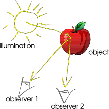
Fig. 1.12 Light reflection. At the surface of the apple, light is reflected in all directions and two of the rays hit the eye of two observers.
Fig. 1.12 shows the reflection of a ray of light at the object surface. The object surface reflects the light in all directions.
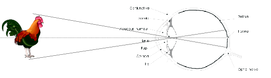
Fig. 1.13 Projection on the retina. The object in front of the eye is projected on the retina.
The ray of light from the surface patch is reflected in the direction of the human eye and projected on the retina: the inner surface of the eye that contains the light sensitive cells (see Fig. 1.13).
The optical principle of the human eye is the same as for any optical camera, be it a photo camera or a video camera. The most simple (but surprisingly accurate) model for such an optical camera is the pinhole camera. This is just a box (you can build one yourself about the size of a shoe box) with a small hole (about half a millimeter in diameter; the easiest way to make one is to use aluminum foil for the side where you have to make the hole) and a photosensitive layer on the opposite side (for the homebuilt pinhole camera you can use a translucent piece of paper: “boterhampapier”). See Fig. 1.14 for a sketch of a pinhole camera.
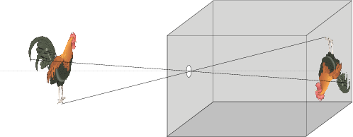
Fig. 1.14 Pinhole Camera. The most simplistic model of an optical camera is a simple box with a hole in it.
Light reflected from an object travels in a straight line through the pinhole and hits the photosensitive surface. The use of optical lenses is a physical trick to enlarge the hole to get more light into the camera without blurring the projected image.
The projection of the 3D world onto the 2D retina of the camera is the cause of many problems in the analysis of the 3D world based on 2D images. In the projection, information about the 3D structure is lost (see Fig. 1.15 showing an image of an `impossible’ 3D object). Reconstruction of the 3D structure from several images of the same scene or from a video sequence is the goal in computer vision.

Fig. 1.15 Impossible Triangle. The triangle is impossible to make, it is not impossible to see one.
Where the rays of light hit the retina we are able to measure the electromagnetic energy and these measurements, as a function of the position on the retina, provide a representation of the image. If we think of the retina as a plane, all positions on the retina are given by \((x,y)\)-coordinates. This results in a function \(f\) whose value \(f(x,y)\) at position \((x,y)\) on the retina (or image plane or image domain) is proportional to the amount of measured energy.
It is impossible to measure the energy in all locations on the retina. We are forced to measure it in a finite number of sample locations. We will consider sampling in another section.
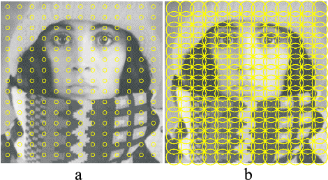
Fig. 1.16 Image Observations. The image can only be observed in a finite number of locations with a probe of finite spatial (and temporal) size (in (a)). The scale (or size) of the probe should be chosen in relation to the distance between the sample points (in (b))
Now let us concentrate on the measurement of the electromagnetic energy in one point on the retina. It is physically impossible to construct a sensor that can observe the electromagnetic energy in a point of zero size. Every sensor has a finite spatial (and temporal) extent (see Fig. 1.16). The observed (measured) luminance in a particular location on the retina is the integration of the spatial energy density in a small neighborhood (called the measurement probe).
The size of the measurement probe should be chosen in accordance with the distances between the individual sample locations. It is useless to have probes that have a size that is much smaller then the distance between samples. In that case the measurements in neighboring sample points are completely independent and there is no clue about the stimulus in between the sample points. A careful choice of the ratio between the sampling distance and the scale of observation is important to be confident that the observer (the human brain or computer that processes the sampled data) doesn’t miss something that happens in between the sample locations.