1. The Pinhole Camera

Fig. 1.26 The human eye projects the 3D visible world on the 2D (curved) retina.
When we look around, the 3D world is optically projected onto the retina (photo sensitive layer) in our eye. The luminance (visual energy) is measured in a lot of photo sensitive cells (the rods and cones) in the retina. The collection of all these measurements makes up an image of what we see in much the same way as a collection of pixels on the screen forms an image.

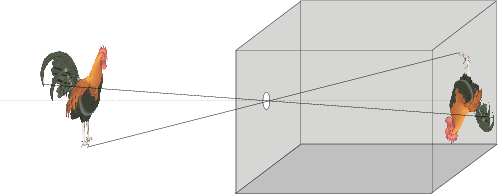
Fig. 1.27 Pinhole Camera. The most simplistic model of an optical camera is a simple box with a hole in it.
The optical principle of the human eye is the same as for any optical camera, be it a photo camera or a video camera. The most simple (but surprisingly accurate) model for such an optical camera is the pinhole camera. This is just a box (you can build one yourself about the size of a shoe box) with a small hole (about half a millimeter in diameter; the easiest way to make one is to use aluminum foil for the side where you have to make the hole) and a photosensitive layer on the opposite side (for the homebuilt pinhole camera you can use a translucent piece of paper: ‘boterhampapier’).

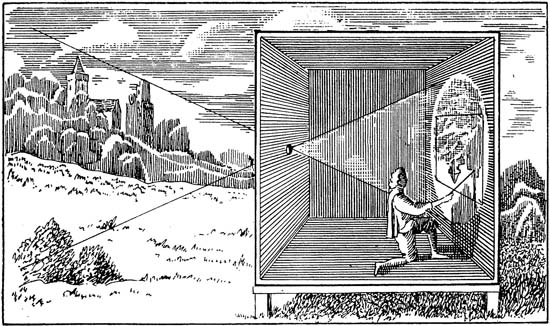
Fig. 1.28 Camera Obscura.
The pinhole camera did exist before analog photography was invented. In those days we did not put a film inside the box but we put a human painter in the box. This is what is called a camera obscura. In Fig. 1.28 a camera obscura is shown (obviously one of the walls is left out in the drawing…). Light enters the ‘box’ from a small hole (the pinhole) on the left. As light rays travel along straight lines 1 the light reflected from one point on the surface of an object in front of the camera obscura (or any other pinhole camera) hits the back wall of the camera obscure in a well defined point. In this way the 3D scene in front of the ‘camera’ is projected on the wall and can be drawn by the artist in the camera.
In the projection of the 3D world onto the 2D retina information about the 3D structure is lost. In this chapter we will look at the mathematics that is needed to model the camera that is used to look at the world with a computer. The ultimate goal of this chapter is to gain enough understanding of the basic workings of a camera to be able to reconstruct the 3D world from 2D images.
In this chapter we will look at:
Based on the observation that the angle between lines is not preserved and that length are not preserved either we will look at projective geometry. Projective geometry deals with the geometrical transformations that preserve colinearity of lines, i.e. straight lines remain straight lines. That is indeed what we (ideally) see when making pictures of the 3D world.
The simplest of all cameras is the pinhole camera. It is based on the fact that light rays travel in straight lines (well almost always, at least for our purposes this is a convenient model).
The camera matrix projects points in 3D onto the 2D retina. We can calibrate the camera using several examples of the 3D-to-2D projection. It will turn out that because of the scaling freedom when working with homogeneous coordinates we cannot use a classical LSQ estimator but we need to approximately solve a homogeneous equation.
When we change the position and orientation of the camera with respect to the 3D scene we are observing then in most situations there is no one to one correspondence of all points in the two images of the same scene. In the section on projectivities we describe two situations in which there is a one to one correspondence between points in two images of the same scene. For image stitching, camera calibration and stereo vision these projectivities play a central role.
Footnotes
- 1
That is only true in special cases as an approximation. Light is bend by large masses (think sun big) for instance. Light going through a very small pinhole is diffracted leading to diffraction patterns instead of a nicely projected point. Also light traveling through an inhomogeneous translucent medium can be bend from a straight path.