5.2.7. Inductors

Fig. 5.12 A picture of soms inductors as a coil of copper wire mostly wrapped around a core.
A piece wire with a current flowing through it becomes a magnet. The electric current induces an electromagnetical field. If we coil up the wire (possibly around a ferrite or metallic core) we get a stronger electromagnet.
It is the interaction of the electrical and magnetical fields that give coils (inductors) there special properties. Not only does the current induces a magnetic field, but when the magnetic field is changing the change in magnetic flux induces a current in the (coiled) wire which opposes the current that induced it.
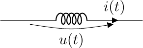
Fig. 5.13 Inductor
It can be shown that the voltage across an inductor is linearly dependent on the change of current through an inductor by:
where \(L\) is the inductance of the inductor measured in Henry’s. Not quite a resistor where \(u=R i\) isn’t it. But consider a sinusoidal alternating current:
then
and this almost looks likes a resistance of value \(\omega L\) for a sinusoidal signal of radial frequency \(\omega\). Almost, because the phase of the signal changed (from sin to cos is a phase change of \(\pi/2\)).
Consider a complex exponential as the current:
then
We call \(j \omega L\) the complex impedance of an inductor. Complex impedances are most often indicated with the letter \(Z\) to distinguish them from ‘simple’ resistors. For an inductor:
Carefully note that the impedance \(j \omega L\) is only valid for a sinussoidal signal of radial frequency \(\omega\). In later sections we will show that any signal (well almost any signal) can be written as a linear combination of complex exponential functions. This is what Fourier analysis of signals is all about.
The nice thing about complex impedances is that we can use them in Ohm’s law as if they were resistance values (keeping in mind that they are complex values of course). The rules for series and parallel connection can be used for inductors as well.