5.2.9. Low Pass Filter
Consider a speaker driven by an amplifier. The sound signal is a AC signal with zero DC component (your speakers wouldn’t like a DC component). There are indeed speakers that are capable of reproducing the full range of audible frequencies (ranging from \(f=20Hz\) to about \(f=20KHz\)). In such cases we can make a direct connection.
But most hifi speakers use different speakers for different ranges of frequencies. Most common are so-called two way speakers, these contain two different drivers (audiofiles make a distinction between a speaker and the drivers it uses, you may call everything a speaker), one for the low frequencies and the second for the high frequencies.
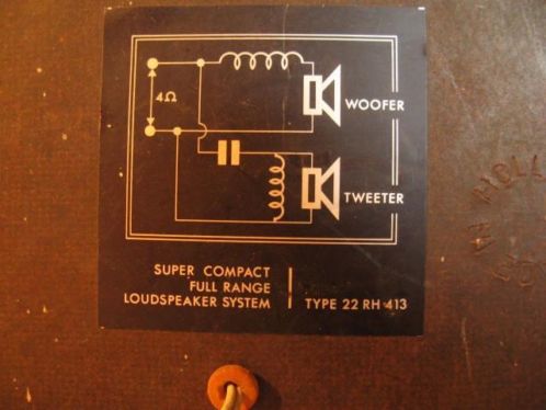
Fig. 5.15 A speaker cross over diagram. Philips used to make quite decent speakers in the old days (you can still find them cheap on Marktplaats or Ebay). In those days Philips was a technology driven company, proud to show how their stuff works. The old speakers had a diagram of the cross-over circuit on the back. The top speaker is the woofer and it only contains an inductor. The capacitor and second inductor are used for the high pass filter.
Here we consider only the low frequency driver (often called a woofer). Of course you can feed it the original (amplified) sound signal but then the speaker has to deal with frequencies it isn’t made for reproducing and in some cases the driver can really be harmed by frequencies it doesn’t like).
So we need a filter to stop all high frequencies. In other words we need a low pass filter. An ideal low pass filter is just an ideal, you can’t make it. Of course you can build a digital low pass filter but that used to be way to expensive for a speaker system. Nowadays you can buy Digital Signal Processing boards especcially made for speaker design. But building a passive filter using inductors, capacitors and resistors is possible and is used in most, even high level, speakers.
A driver is most often modelled as a resistor with resistance \(R\). A simple low pass filter then can be made by just putting an inductor in series with the speaker.
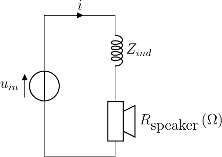
We are then interested in the transfer function \(u_{speaker}/u_{in}\). We can treat this as a voltage divider if we replace the resistors with the complex impedances.
We get a nice impression of the frequency response of this low pass filter when looking at the Bode plot (i.e. \(|H(\omega)|\) plotted on a double logarithmic scale). Be sure you can reproduce the plot given that \(R=8\Omega\) and \(L=0.68mH\).
Show code for figure
 1import numpy as np
 2import matplotlib.pyplot as plt
 3
 4plt.clf()
 5
 6R = 8
 7L = 0.68E-3
 8
 9w = np.logspace(-1,5,num=1000)
10H = R / (R+1j*w*L)
11
12plt.plot(w, abs(H))
13plt.xscale('log')
14plt.yscale('log')
15plt.xlabel(r'$\omega$')
16plt.ylabel(r'$|H(\omega)|$')
17plt.savefig('source/figures/bodeabsplotlowpass.png')
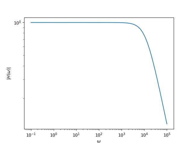
Fig. 5.16 Bode plot of low pass filter.
We can use some rules of thumbs to sketch the Bode plot. For small frequencies, \(\omega\rightarrow0\), we have \(H(\omega)=1\), for large frequencies, \(\omega\rightarrow\infty\) we have \(H(\omega) = -j \frac{R}{\omega L}\). Thus for low frequencies \(\log | H(\omega)| = 0\) and for high frequencies \(\log | H(\omega)| = \log(R/L)-\log(\omega)\).
On a log-log scale plot these are both straight lines. These lines intersect when \(\omega = R/L\). Convince yourself that this simple analysis is indeed what you see in the calculated plot. The frequency \(R/L\) is called the cross over frequency of this low pass filter. This filter is called a first order filter as the radial frequency occurs linearly in the formula (exponent 1).
In an exercise you are asked to plot the phase change of the filter. In speaker design one strives for as little phase change as possible.
The low pass filter detailed here is the simplest of them all. We can make more complex filters. In an exercise you are asked to make a second order low pass filter by adding a capacitor to the filter.