5.2.13. Measurements
When building and testing electronic equipment invariable the need arises to measure voltages and currents. Either constant values (with a multimeter) or time varying signals (with an osciloscope).
Again this section is not meant to be a guide for using a multimeter or oscilloscope. It only hightlights some of its uses.
5.2.13.1. Multi-meter
A multimeter (see figure below) is primarily used for measuring voltages and currents.

Fig. 5.27 Multimeter. This multimeter is an autoranging meter where you only have to select what you want to measure (voltages, currents and for this meter also resistance and frequencies), the range for the measurement is automatically selected.
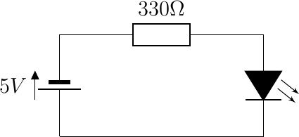
Consider the simple circuit to lighten up a red LED.

Fig. 5.28 Lighting up a LED.
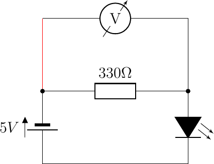
In case you want to measure the voltage drop over the resistor you place the red probe on the left side of the resistor and black probe on the right hand side of the resistor. The circuit now is shown below.

Fig. 5.29 Lighting up a LED and measuring the voltage across the resistor.
The meter will measure a positive voltage. In case you interchange the red and the black probe the measured voltage just changes sign. As always in electronics, your measurement device influences the circuit you are measuring. In this case you effectively replace the \(330\Omega\) resistor with the parallel connection of that resistor and the internal resistor of the multimeter. Multimeters are designed to have a very large input impedance (resistance) and thus the total resistance is almost \(330\Omega\). In that way the influence of the meter on the circuit (and thus on the measurement is minimal).
In the same way you can measure the voltage across the LED and if all is well the two voltages add up to the voltage supplied by the battery (according to Kirchhoffs voltage law).
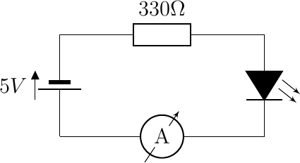
In case you want to measure the current trough the LED you have to break the circuit and put the current meter (switch the multimeter to a position for measuring currents) in the loop.

Fig. 5.30 Lighting up a LED and measuring the current in the loop.
For the current meter not to influence the circuit the internal impedance now should be very low so the voltage drop across the meter is negligible. Most often a current meter really is the parallel combination of a high precision very low resistance with a very accurate voltmeter (and then using Ohm’s law to calculate the current).

Especially when measuring currents you should be really really careful and know what you are doing. Most multimeters are not capable of safely measuring high currents.
The multimeter is used to measure both AC as well as DC voltages and currents. But for AC voltages and currents it is assumed that it is steady signal, either a pure sinusoid or other type of one-frequency signal. Instead of really measuring the time dependency the effective voltage/current is measured as discussed in the section on power (so for the mains electricity network a well designed multimeter, often designated as measuring True-RMS AC voltages, will measure 230V.
5.2.13.2. Oscilloscope
An oscilloscope is meant to measure and visualize time varying voltages. Traditionally a scope visualizes periodic signals as in the old days there was no way to store signals in some kind of memory; signals were visualized in real time. A lot of the terminology needed to operate a scope is from that time.
For an introduction to the use of an oscilloscope we refer to the web where many YouTube video’s and other resources are available. Here we only give a brief description of the scope used in the lab for this course.

Fig. 5.31 Oscilloscope used in DSP Lab.
The important sections of the user interface of the scope are:
The display where the signals are displayed alongside with the measurements by the scope like frequency of the signal and peak to peak voltage of the signal.
Just to the right of the display are the 5 buttons for the on-screen menu (on the right of the screen).
Todo
Taco’s handleiding??