5.2.2. Serial Circuits / Voltage Divider
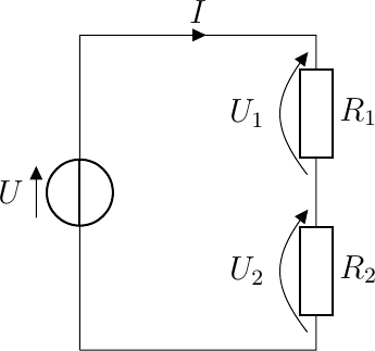
Fig. 5.8 Serial connection of two resistors
Consider a circuit with two resistors in series. Again it is a closed circuit and current will flow. The same current will flow through both resistors. Using Ohm’s law we then can calculate the voltages across the resistors:
The total voltage across both resistors is \(U_1+uU2\) and is equal to the battery voltage \(U\). So:
i.e. the two resistors in series act as one resistor with resistance \(R = R_1+R_2\).
Our analysis above can be done for an arbitrary number of resistors in a serial circuit.
In a serial circuit the current through all resistors is the same, the voltage across each resistor is dependent on its resistance (relative to all other resistors in the circuit).
The serial circuit serves as a voltage divider. In a more systems oriented view of the same circuit we can draw it as shown below.
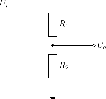
Note that it appears that the circuit in the figure above does not contain a loop and thus no current can flow. However in these types of circuits it is implicitly assumed that the indicated voltages (\(U_i\) and \(U_o\)) are with respect to ground (the arrow like symbol at the bottom of the circuit).
It is not hard to prove that