5.2.11. Operational Amplifiers
In analog electronics, including signal processing, operational amplifiers are very important components. These are active components in contrast to the passive components we have seen so far. As such they are really outside the scope of these lecture series. We only give a very brief introduction as we need an op amp in one of the circuits in the practical course and because opamps are a very nice example of the use of feedback in signal processing systems.
An opamp can amplify voltages and currents and thus increase the power. That power has to come from a powersource. The opamp is an active electronic element just like the bare transistor. A more formal drawing is:
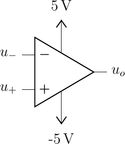
This opamp is ‘fed’ by a dual rail power source supplying both \(+5\) and \(-5\) Volt. The inputs \(u_{+}, u_{-}\) and output \(u_o\) all have to be within the range of the supplied voltages. No matter what the inputs are, the output is always clipped in the interval of supplied voltages.
It is possible (and indeed used a lot) to use \(0\) and \(5\) Volt as supplied voltages but than the opamp cannot give negative voltages as output. Something to be reckoned with if you mix digital and analog signals.
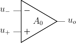
Functionally an opamp amplifies the potential difference at the input \(A_0\) times. I.e. \(u_\text{out} = A_0 (u_{+} - u_{-}) \) . The open loop amplification factor is very high, in the order of \(10^5\). Approximately we can take it to be infinitely large. We call it an ideal opamp.
Fig. 5.18 Operational Amplifier (OpAmp). The open loop gain of the amplifier is given by \(U_0 = A_0(u_{+} - u_{-})\). Typically \(A_0\approx10^5\).
As an open loop amplifier an opamp is of little use. The output will be clipped by the power supply and that even for very small potential difference at the input. The opamp shines in case we use it in a feedback configuration.
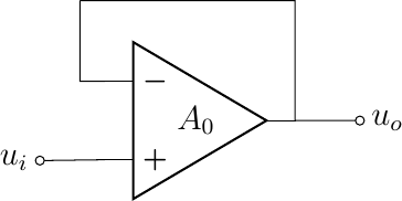
The easiest feedback loop configuration is the opamp with unity gain, i.e. \(u_0 = u_i\).
Fig. 5.19 Unity gain negative feedback loop.
To calculate the transfer function \(u_o/u_i\) for this opamp configuration note that:
so
i.e.
and thus
and for (very) large \(A_0\) we have
This circuit is also called a buffer or a unity gain amplifier. It more or less makes the circuitry that ‘makes’ \(u_i\) (the input) and the circuitry that uses \(u_0\) (the output) independant of each other.
Note that for \(A_0\rightarrow\infty\) we have that \(u_- = u_+\) and thus that no current is flowing into (of out of) the opamp through its inputs. These two observations can be proven to characterize circuits with opamps that are more complex than the simple unity gain amplifier. These observations are the principles of the ideal opamp:
Consider the following opamp circuit where both \(u_i\) and \(u_o\) are measured with respect to ground.
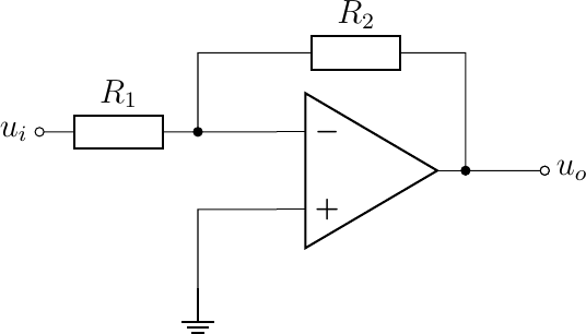
Fig. 5.20 Inverting Amplifier.
Applying the rules of the ideal opamp we get that \(u_-=0\) (a virtual ground). Given that no current is flowing into (or out of) the opamp, i.e. \(i_-=0\) we have that the current flow \(i_1\) through \(R_1\) equals the current \(i_1\) through \(R_2\) and applying Ohm’s law we have
leading to
Note that again the properties of this opamp circuit are not dependent on the opamp parameter \(A_0\). This is a good thing in practice as the open loop amplification is not constant over opamps (even of the same type) and for any opamp is dependent on temperature and other parameters. The use of negative feedback stabilizes the properties of the opamp circuit.
In an exercise you are asked to calculate the transfer function for a non inverting opamp.
Most OpAmps can amplify DC signal as well as AC signals. It depends on the type op opamp what is bandwidth is. This capability can be used to build frequency dependent opamp circuits by introducing capacitors (and sometimes even inductors) in the feedback loop of an opamp circuit.
Operational amplifiers can also be used to add signals. Consider the following extension to the inverting amplifier showing a way to mix three different audio signals.
Fig. 5.21 Mixing Audio Signals. A summing opamp is used to mix three audio signals.
Note that the US style for resistors is used (the squigly line) and that a resistor with an arrow pointing to it is variable voltage divider (a potentiometer). The capacitors at the input are used to decouple the amplifier from any DC signal in the inputs.
A summation circuit using an opamp is also used in a traditional DAC (Digital to Analog Converter). Note that logical signals ‘’1’’ are represented with a constant voltage (often 5 Volt) whereas a digital ‘’0’’ is represented with a zero voltage level.
Fig. 5.22 DAC Ladder Converter. A summing opamp configuration used to convert digital into analog.