Analog Filters
An analog LTI filter takes a signal \(x(t)\) as input and produces output signal \(y(t)\) being the convolution of \(x(t)\) and the impulse response \(h(t)\).
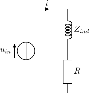
Many analog filters are designed with analog electronic circuits. We have seen some examples in the chapter on analog electronics. E.g. a first order low pass filter for audio application is realized with an inductor of inductance \(L\) in series with the load (speaker) of resistance \(R\).
In the s-domain the transfer function \(H(s)\) is given by
Remember that its frequency response is:
The canonical low pass filter is given as:
Analog filters are often designed and specified in the complex s-domain in the form of the complex transfer function \(H(s)\) being the Laplace transform of the impulse response function.